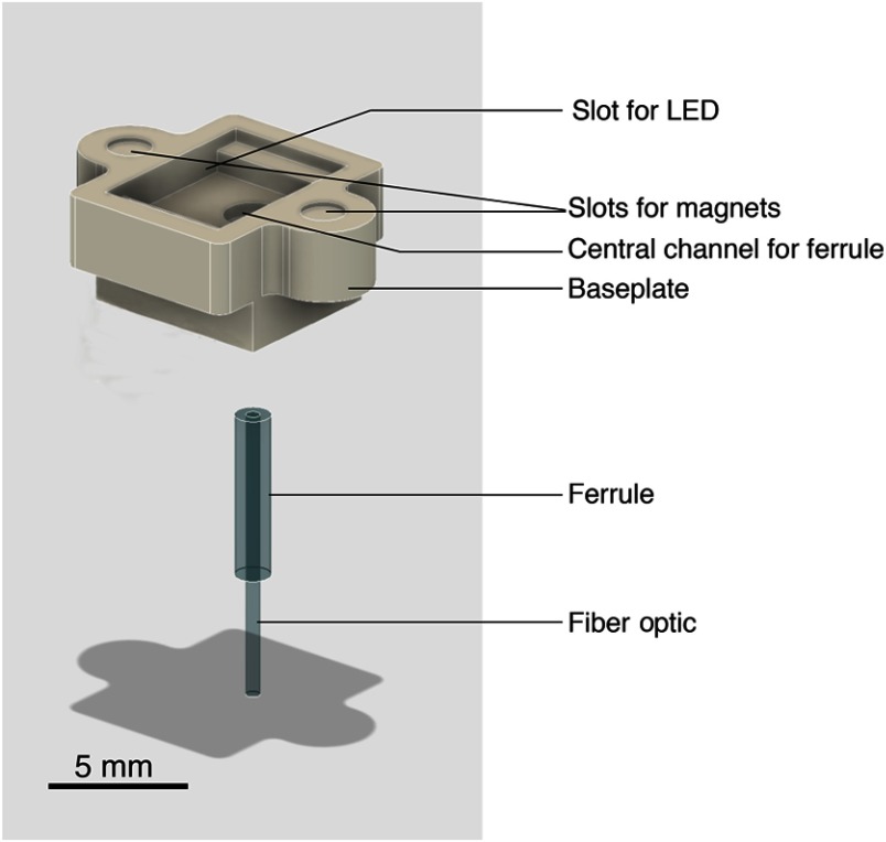
Fig. 2.
Overview of the optics component on the CerebraLux probe. This schematic shows greater detail of the optic component. The milled baseplate has slots for the magnets, LED, and fiber-optic. The alignment magnets are glued into their respective slots, and the fiber-optic and ferrule are inserted in the central channel of the baseplate. The LED is on the underneath of the PCB and aligns magnetically into the upper slot in the baseplate. This component is inserted into the correct region of the skull using a milled stereotaxic adapter that also has two aligning magnets (Appendix, CerebraLux manual; Sec. A1.5).

