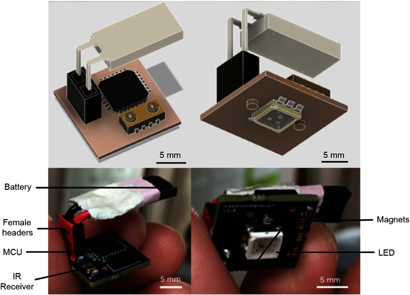
Fig. 5.
The electronic component of CerebraLux. A fully assembled PCB is shown here. The battery, female headers, MCU, and IR receiver are on the upper side of the PCB and are shown in the left panels with the schematic in the top panel and the device in the lower panel. The magnets and LED are on bottom portion of the PCB. This view is shown in the right panels with the schematic view in the top panel and the device in the lower panel. The module has a footprint of and, along with female headers and battery, has a weight of 2.3 g. This includes magnets that align with and attach to those on the baseplate of the optic component.

