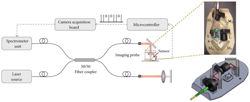
Figure 1.
Schematic of the proposed imaging system. The hand-held imaging probe in the sample arm contains the motion sensor (cyan box) and the optics for focusing the OCT beam into the sample. The OCT beam path is shown in red in the SolidWorks rendering of the hand-held imaging probe. C: collimator, M1–M4: mirrors, L: focusing lens, P: right-angle prism, and S: motion sensor.

