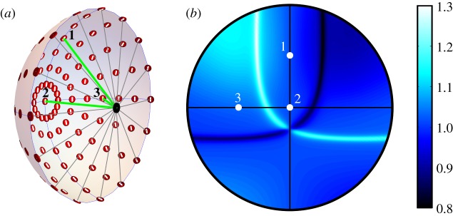
Figure 3.
(a) Schematic representation of an eye showing representative AB pairs of photoreceptor cells (red discs) distributed around the retina, modelled as a hemisphere with the pupil (black spot) at its centre. The white line through of each of the red discs indicates the direction of the TDM (ym axes) in the two cells (figure 1c). Three rays of light are shown entering the eye through the pupil and hitting the retina at points 1, 2 and 3. The photoreceptor cells are arranged with the symmetry (zc) axis of each cell pointing towards the pupil and the xc axes following the lines of longitude of the sphere, taking the pupil and the centre of the retina as points on the sphere's equatorial plane. (b) An equal-angle projection of the ratio (A/B) of the outputs of the array of cell pairs showing the reference points 1, 2 and 3. The eye looks horizontally to magnetic north. For this simulation, the sun was on the horizon in the west and the maximum polarization was 75%. This is essentially the same pattern as shown in figure 2e.

