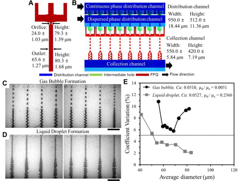
Fig. 1.
Schematic diagram for the ladder geometry design of 3D MED. (A) Geometry of FFG and dimension variation in 8 orifice and outlet channels. (B) 8 parallel bubble generation to investigate factors affecting size distribution. Optical micrographs of formation of gas bubbles (C) and liquid emulsion (D) in 8 parallel FFGs. Scale bars are 500 µm. See Electronic Supplementary Information for the movies. (E) Comparison of CV for gas bubble and liquid emulsion generation in 8 parallel FFGs.

