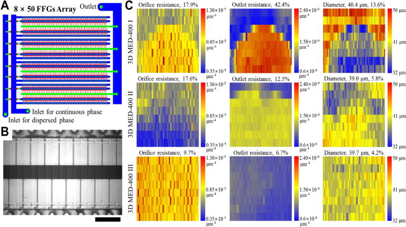
Fig. 3.
Large-scale integration of 400 FFGs for mass production of gas bubbles and the effect of channel dimension variations on the uniformity of gas bubbles. (A) The ladder-form 3D MED design contains 8 rows by 50 columns of FFGs. (B) Gas bubbles are produced by using the optimal flow conditions as determined using the 8-FFG 3D MED (See Supporting Information for movie). Scale bar indicates 1 mm. (C) Heat maps showing the channel resistance variations. Each rectangle in the heat maps represents a FFG. The first and second columns show the flow resistances of the orifice and outlet channels, respectively, and the third column shows the size of bubbles generated from 400 FFGs in 3D MED-400 I, II and III.

