FIGURE 1:
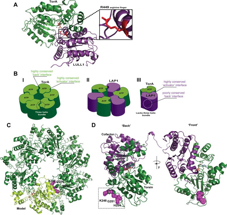
Models of Torsin’s functional assembly and identification of a conserved region at the “back” interface. (A) TorsinA forms a tightly apposed, ATP-dependent interface with its cofactors (here, LULL1) LDs whereby an arginine finger (red) from the cofactor can coordinate the γ-phosphate of ATP. Representation based on the LULL1-TorA crystal structure (PDB code 5J1S, nanobody used for crystallization omitted for clarity). (B) Three different models exist for the active assembly of Torsins: (I) a homo-oligomeric (likely hexameric) ring; (II) an alternating trimer of dimers; (III) a Torsin-LAP1LD heterodimer. (C) Model of a homohexameric Torsin ring based on the crystal structure of TorsinA (PDB code 5J1S). A highly conserved region at the “back” interface of each TorA monomer (light green cartoon) contains residues 248, 251, and 254 (magenta spheres) likely contributing to intraprotomer contacts. Bound ATP is shown in stick representation. (D) An ATP-bound Torsin (dark green)-cofactor (purple) complex showing the “back” interface with predicted intraprotomer contact sites at residues K248, G251, and H254 (magenta spheres) and the “front” interface. Representation based on the LULL1-TorA crystal structure (PDB code 5J1S).

