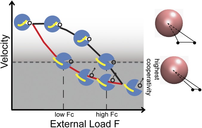
Fig. 5.
A schematic force–velocity diagram with cartoons showing the spatial arrangement between the neck linker (yellow) and the motor head of a leading kinesin (blue spheres). The black open circles represent ATP. The upper black curve denotes the motion of a WT kinesin with a neck linker that detaches from the motor head at a force close to the stall force. The lower red curve denotes the motion of a kinesin mutant with a neck linker that detaches from the motor head at a force much lower than the stall force. Fc is the total force on the two interacting kinesins in a triangular configuration when the two are at the smallest separation on an MT, reaching a possibly highest cooperativity. Two WT kinesins reach this highest cooperativity at a higher external load than the two mutants.

