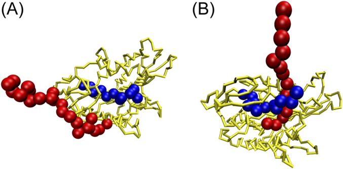
Fig. S4.
Different relative positions of a disordered neck linker with respect to a motor head. The neck linker is colored in red. The N terminus of the motor head is colored in blue, and the rest part is colored in yellow. (A) In this work, the neck linker was placed outside the N terminus of the motor head. (B) In the prior work (13), the neck linker was modeled between the N terminus and the rest part of the motor head.

