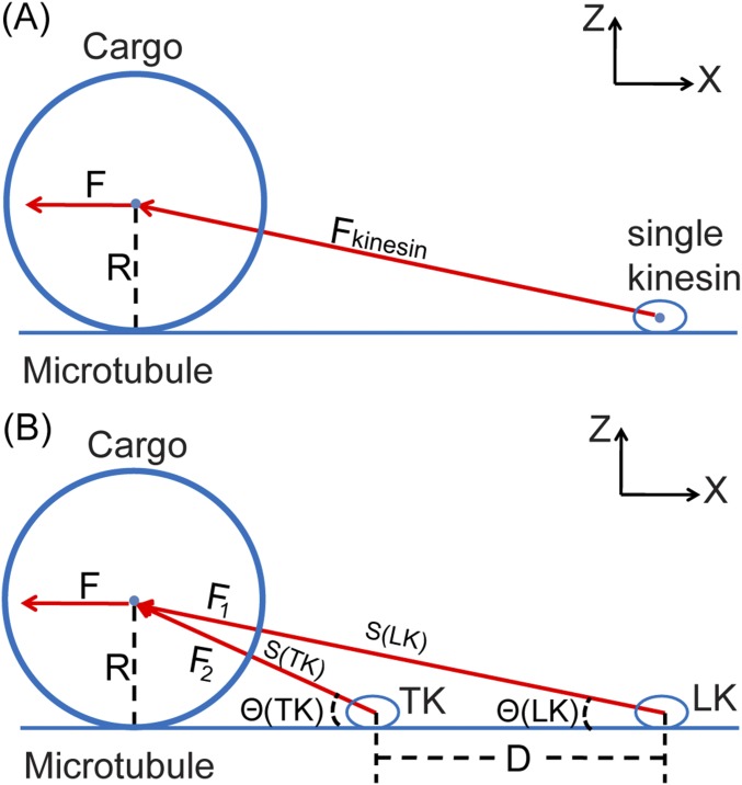
Fig. S7.
Illustration of (A) a single load-bearing kinesin that carries a cargo on the MT and (B) an LK and a TK jointly sharing an external load from a cargo on the MT. R is the radius of the cargo. F is the external loading force pointing to the –X direction. For A, Fkinesin is the force exerted by the single kinesin on the center of mass of the cargo. For B, F1 is the force exerted by the LK on the cargo. F2 is the force exerted by the TK on the cargo. θ(LK) is the angle between F1 and F. θ(TK) is the angle between F2 and F. D is the distance between the two kinesins. S(LK) is the distance between the center of the cargo and the LK. S(TK) is the distance between the center of the cargo and the TK.

