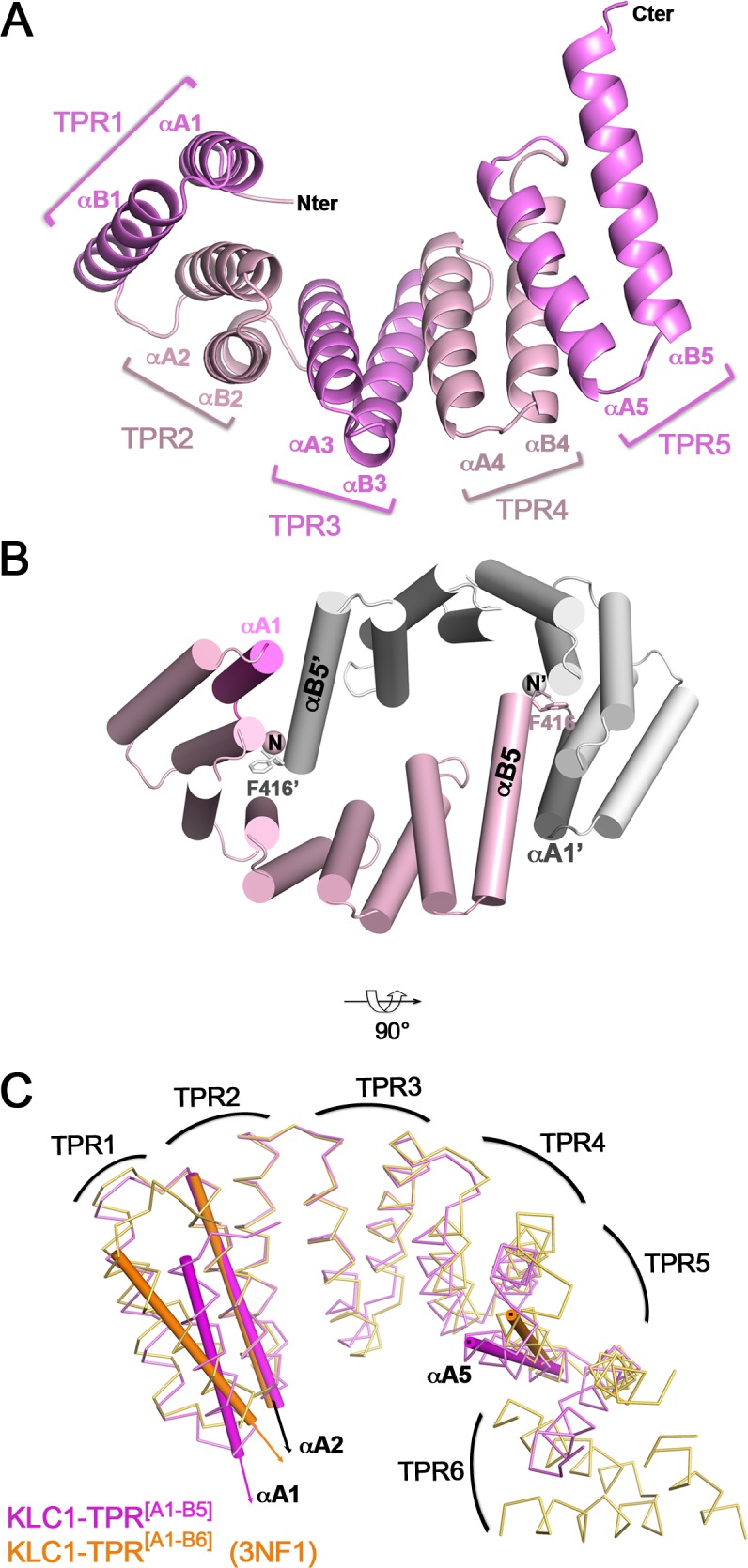
Fig 3. Crystal structure of a C-terminal truncated TPR domain of KLC1.

(A) 3D structure of KLC1-TPR[A1-B5]. (B) Cartoon representation of the αA1:αB5’-sym crystal packing contact. The A1 helix is indicated in magenta. The crystal contact molecule is coloured in white and a labelled with an apostrophe. The Phe416 residue is shown in sticks. (C) Superposition of KLC1-TPR[A1-B5] (this study, pink) and KLC1-TPR[A1-B6] (3NF1, orange; the N-terminal His-tag is removed for clarity) structures. TPR domain superposition is done on the TPR2 motif. The axes of A1, A2 and A5 helices are indicated with thin cylindrical tubes. The TPR domain curvature and the αA1 orientation can be observed by comparing the αA5 and αA1 axes to the reference αA2 axis.
