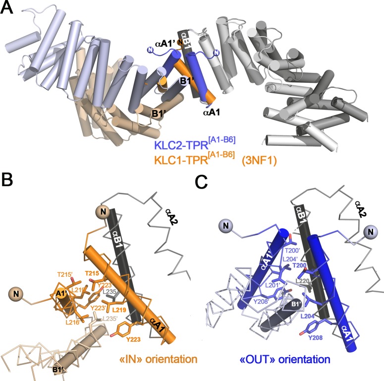
Fig 6. The TPR1:TPR1’ crystal packing contacts.
(A) Superposition of KLC2-TPR[A1-B6] (this study, blue) and KLC1-TPR[A1-B6] (3NF1, orange). TPR domain superposition is done on the B1 helix of the main molecule. For clarity, only the TPR domain of KLC2-TPR[A1-B6] (this study) is shown in grey in a cartoon representation as a template, but A1 helices are shown in color. The symmetry molecule at the TPR1:TPR1’ contact is shown in color. A 180° view is shown below. (B) Zoom at the TPR1:TPR1’ contact for the KLC1-TPR[A1-B6] crystal form (3NF1, orange). (C) Zoom at the TPR1:TPR1’ contact for the KLC2-TPR[A1-B6] crystal form (this study, blue). The orientation is conserved between (B) and (C) with the reference B1 helices (grey) indicated with a black axis. Some residues involved in the TPR1:TPR1’ contact are indicated in sticks.

