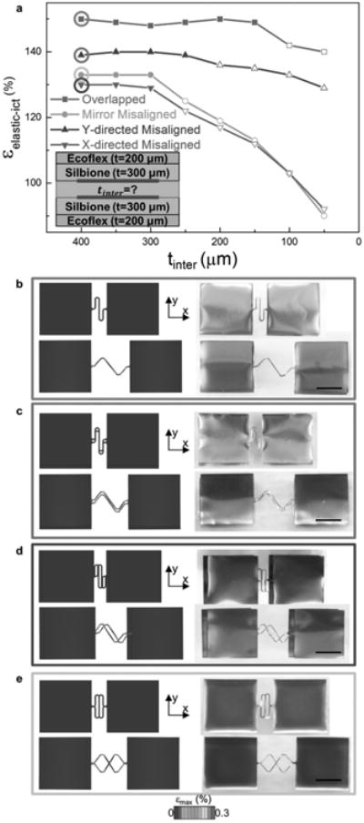
Figure 2.

Design optimization of silicone interlayer between interconnects, guided by numerical and experimental results. a) The elastic stretchability of interconnects versus the interlayer thickness, for interconnect pairs with and without misalignments. b–e) FEA and optical images of initial (top) and deformed (bottom) interconnects, when the two interconnects involved are vertically overlapped (b), misaligned by 300 μm in y direction (c), misaligned by 300 μm in x direction (d), and mirrored (e). The deformed interconnects were all stretched toward their elastic stretchabilities. The color in FEA images denotes the maximum principal strain in metal. (Scale bars: 250 μm).
