Fig. 1.
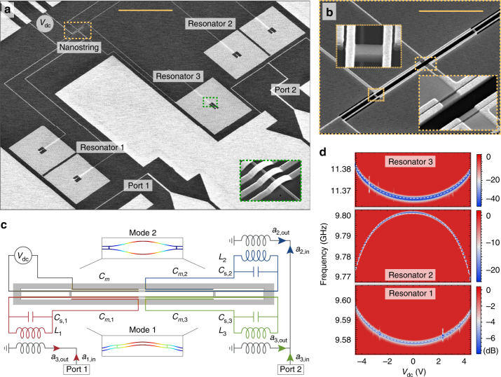
Microchip circulator and tunability. a Scanning electron micrograph of the electromechanical device including three microwave resonators, two physical ports labelled 1 and 2, one voltage bias input (V dc) on the top left. The inset shows the spiral inductor cross-overs in the green dashed boxed area. The total device area is 0.3 mm by 0.45 mm. Scale bar (yellow) corresponds to 100 μm. b Enlarged view of the silicon nanostring mechanical oscillator with four vacuum-gap capacitors coupled to the three coil inductors and one voltage bias input. Insets show details of the nanobeam as indicated by the dashed and dotted rectangles. Scale bar (yellow) corresponds to 10 μm. c Electrode design and electrical circuit diagram of the device. The input modes a i,in couple inductively to the microwave resonators with inductances L i, coil capacitances C i, additional stray capacitances C s,i and the motional capacitances C m,i. The reflected tones a i,out pass through a separate chain of amplifiers each, and are measured at room temperature using a phase-locked spectrum analyzer (not shown). The simulated displacement of the lowest frequency in-plane flexural modes of the nanostring are shown in the two insets. Colour indicates relative displacement. d Resonator reflection measurement of the three microwave resonators of an identical device, as a function of the applied bias voltage and a fit (dashed lines) to Δω = α 1 V 2 + α 2 V 4 with the tunabilties α 1/2π = 0.53 MHz/V2 and α 2/2π = 0.05 MHz/V4 with a total tunable bandwidth of 30 MHz for resonator 2 at 9.8 GHz

