Fig. 2.

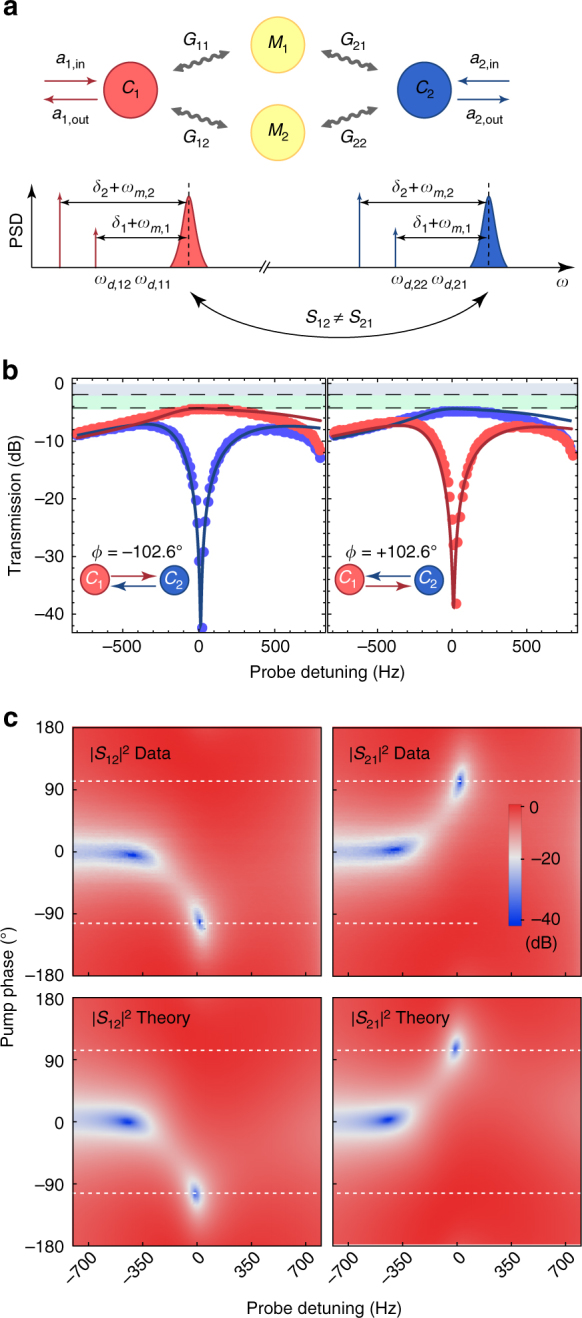
Electromechanical isolator. a Mode coupling diagram for electromechanically induced nonreciprocity. Two microwave cavities (C 1 and C 2) are coupled to two mechanical modes (M 1 and M 2) with the electromechanical coupling rates G ij (where i, j = 1, 2), inducing two distinct signal conversion paths. Power spectral density (PSD) of the two microwave cavities and arrows indicating the frequency of the four microwave pump tones slightly detuned by δ i from the lower motional sidebands of the resonances. All four pumps are phase-locked while the signal tone is applied. Only one of the microwave source phases is varied to find the optimal interference condition for directional transmission between ports 1 and 2. b Measured power transmission (dots) in forward |S 21|2 (cavity 1 → cavity 2) and backward directions |S 12|2 (cavity 2 → cavity 1) as a function of probe detuning for two different phases ϕ = ±102.6º. The solid lines show the results of the coupled-mode theory model discussed in the text. Grey shaded areas denote cavity loss and green shaded areas insertion loss. c Experimental data and theoretical model of measured transmission coefficients |S 12|2 and |S 21|2 as a function of signal detuning and pump phase ϕ. Dashed lines indicate the line plots for the two phases ϕ = ±102.6º as shown in b
