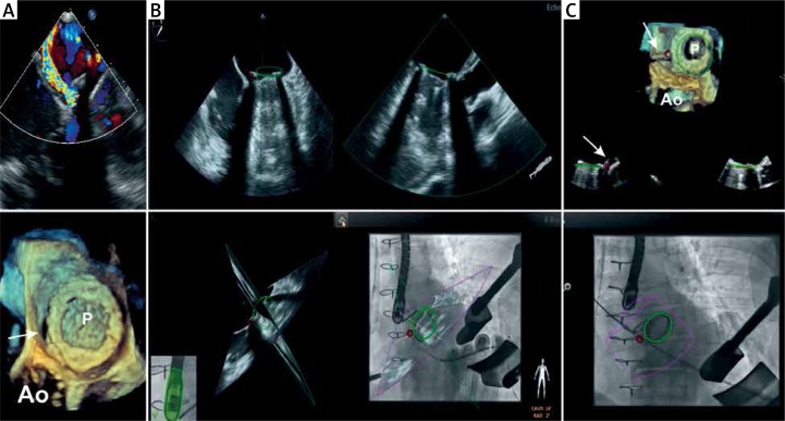
Figure 2.
Patient 2 periprocedural fusion of fluoroscopy and real-time 3D TEE. A – The preprocedural color flow Doppler (top) and 3D images (bottom) demonstrates bileaflet mechanical mitral valve prostheses (P) and the paravalvular leak located at 2 o’clock (arrow). B – Two dimensional X-plain images (top), X-plain echo images are oriented according to C-arm position (left bottom) and are fused with the fluoroscopy image (right bottom). Position of the prostheses is marked by a green circle in all images. The red circle identifies the location of the defect. C – Guidewire passage through the paravalvular defect. The fluoroscopy image (on the bottom) demonstrates wire crossing the red circle; 3D TEE image (top) confirms the guidewire passage through the defect. The arrow in the 3D TEE image shows the guidewire crossing the defect
Ao – position of the aorta.

