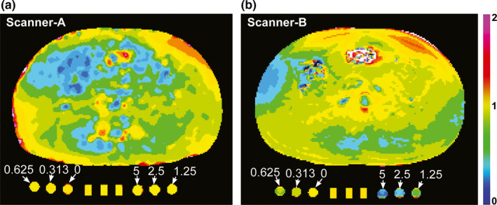
Figure 3.

Normalized flip angle (FA) maps. (a, b) Normalized FA maps of a volunteer (Volunteer 2) and the phantom package containing a perfusion phantom comprised of three components at the center and a static phantom comprised of six components with varying contrast concentrations (0~5 mM), when (a) Scanner‐A or (b) Scanner‐B were used. Normalized FA is the ratio of the measured FA to the original FA set by the operator.
