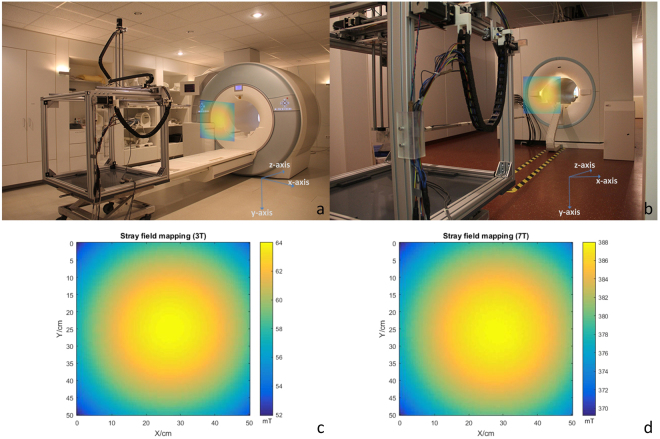
Figure 8.
Stray field mapping setup and results. (a) Stray field mapping setup in the 3 T scanner room, a 50 × 50 cm square transverse slice 90 cm outside the bore was selected. (b) Stray field mapping setup in the 7 T scanner room, a 50 × 50 cm square transverse slice 90 cm outside the bore (from the back side of the scanner) was selected. (c) Stray field mapping results (vector magnitude) of the selected slice for the 3 T scanner (spatial resolution: 5 mm). (d) Stray field mapping results (vector magnitude) of the selected slice for the 7 T scanner (spatial resolution: 5 mm).

