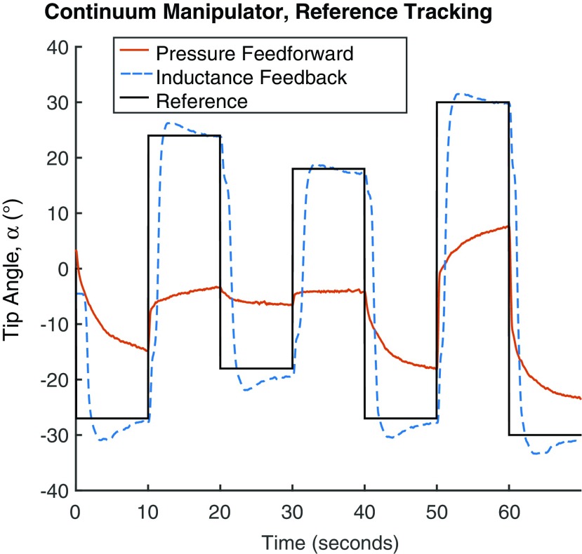
FIG. 15.
Shown are the tip angles of the continuum manipulator as recorded by the camera during two trials. The inductance feedback controller allowed the continuum manipulator to track the reference input with an RMS of  in the steady-state error (evaluated in the last 5 s of the step). Supplementary Video S1 (Supplementary Data are available online at www.liebertpub.com/soro) includes a recording of the inductance feedback trial. Color images available online at www.liebertpub.com/soro

