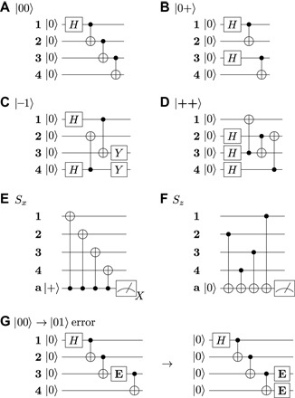
Fig. 2. Circuit diagrams.

(A to D) Circuits for the encoding of four different logical states constructed such that logical qubit La is prepared fault-tolerantly. Any logical state can be achieved by applying single logical qubit operators to states encoded as shown here. (E and F) Circuits for the two stabilizers Sx and Sz, which project Z- and X-type errors, respectively, onto an ancilla qubit a. Note that a controlled Z-gate is realized by an inverted CNOT with the ancilla in the Z-basis as the target. (G) Example of fault-tolerant construction of circuits for logical qubit La: The encoding circuit for |00〉L has a single nondetectable error channel. A bit-flip error E occurring as shown can change the state to |01〉L, which is an error on the logical gauge qubit Lb. Logical qubit La is prepared fault-tolerantly. This property holds for all circuits (A to F).
