
Figure 10. Reaction times, quantum yields and electron-transfer reorganization energies in CPD repair by photolyases.
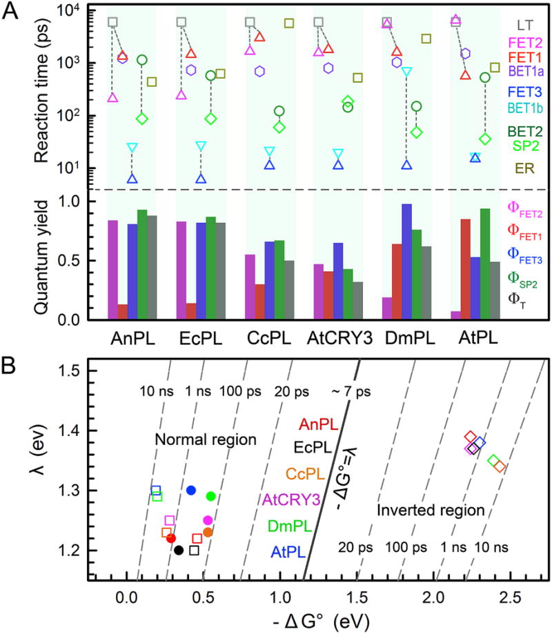
(A) Top: Reaction times of all elementary steps involved in repair by different photolyases. LT, deactivation lifetime; FET1, forward electron transfer (ET) to adenine; FET2, forward ET directly to substrate; FET3, forward ET from anionic adenine to substrate; BET1b, back ET from anionic adenine to flavin ground state; BET2, back ET from anionic substrate to flavin ground state without repair; SP2, the C6–C6′ bond splitting; ER, electron return after repair. The C5–C5′ bond cleavage is ultrafast and is not shown here. The dashed lines link three sets of competing branching channels responsible for the repair efficiencies. Bottom: Elementary quantum yields (QYs) of three forward ETs and SP2, and the total repair quantum yield ΦT for each photolyase. The four elementary QYs are calculated as follows: ΦFET1=<τFET1>−1/(<τLT−1+<τFET1>−1 +<τFET2 >−1; ΦFET2+<τFET2>−1/(τLT−1+ +<τFET1>−1 +<τFET2>−1); ΦFET3=+<τFET3>−1/(<τFET3>−1+<τBET1a>−1+<τBET1b>−1); ΦSP2=<τSP2>−1/(<τSP2>−1+<τBET2>−1). Because the ET between LfH−* and adenine interconverts, the overall repair QY is calculated as ΦT= (ΦFET2+ ΦFET1× ΦFET3)× ΦSP2×(1+Φ′+Φ′2 +Φ′3…), where Φ′=ΦFET1×[<τBET1a>−1/(<τFET3>−1+ <τBET1a>−1+ <τBET1b>−1)]. In all photolyases studied here, Φ′ is less than 0.01 due to a much faster τFET3 than τBET1a. (B) Two-dimensional (2D) contour plot of the ET dynamics in repair relative to free energy (ΔG0) and reorganization energy (λ) for FET2 (filled circle), BET2 (open square) and ER (open diamond). The FET2 is in the Marcus normal region (−ΔG0≤ λ) and the ER is in the Marcus inverted region (−ΔG0> λ). BET2 is a dissociative ET process and is in the normal region again.