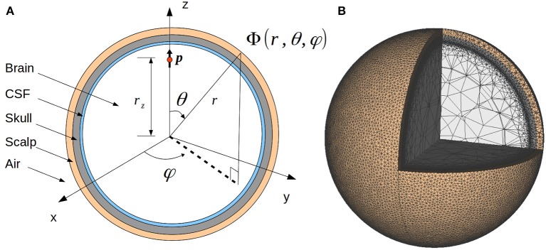
Figure 1.
Illustration of the four-sphere head model. (A) Cross-section of the four-sphere head model, with the different colors corresponding to the different head layers: brain, CSF, skull, and scalp. The current dipole p is located in the brain layer, at a distance rz from the center of the sphere. In all the subsequent figures, the dipole is placed in the x = 0 plane, at the z-axis (rz = 7.8 cm). (B) Mesh of the four-sphere model used in the FEM simulations illustrating the different electrical conductivity values for each of the spheres.

