
Figure 3.
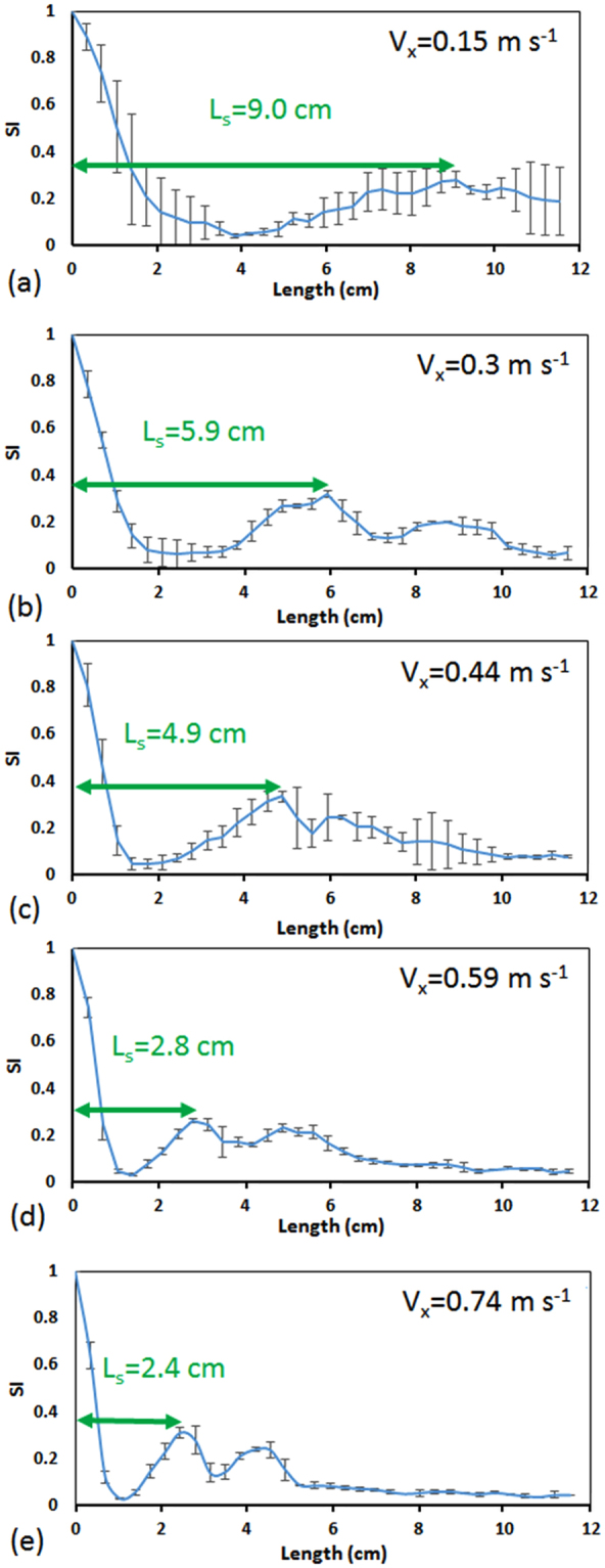
Switching Index (SI) diagrams along the length of the channel at various inlet axial velocities, Vx, of methylene blue and water that were co-injected into a device with R = 2 cm and cross section area of 150 µm × 150 µm. SI decreases along the channel as the two solutions form counter-rotating vortices and increases when they start separating from each other into distinct phases again downstream the channel. The first peak in the SI plot indicates the exact location of the first switch in position (Ls) of methylene blue and water solutions (i.e., 180° recirculation). At higher axial velocities, a second switch corresponding to a full 360° recirculation of fluids can be clearly seen. Error bars represent the standard deviation of three experimental repeats.