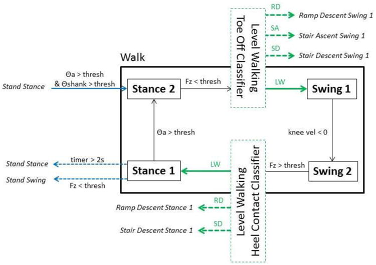
Fig.1.

A portion of the finite state machine is shown for walking mode only. Within-mode transitions that occurred based on mechanical sensor data are shown with black arrows. Between-mode transitions that occurred based on mechanical sensors are shown with blue arrows. Between-mode transitions that occur based on the execution of a key fob or a pattern recognition classifier are shown with green arrows. Walking mode transitions are displayed with solid lines and all outgoing ambulation mode transitions from walking mode are displayed with dashed lines.
