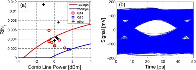
Figure 3.
(a) Prediction of laser characteristics required to achieve error free (BER < 10−12) 14 and 25 Gbps modulation for the link architecture shown in Fig. 1 (red and blue curves) and comparison to the results of the system experiments: Markers show the experimentally recorded comb line characteristics. Red and blue markers represent the 8 consecutive comb lines with which 14 and 25 Gbps error free operation has been respectively achieved. Black markers correspond to lines for which BER has not been measured and are included to provide a complete picture of the MLL characteristics. The curves serve to classify the dots in regards to expected performance based on model predictions: dots below the red curve are predicted to reach 14 Gbps error free and dots below the blue curve are predicted to reach 25 Gbps error free. (b) Real time transmitter eye diagram recorded at 25 Gbps with the 1543.8 nm MLL line (blue marker in (a)). Note that the commercial photo-receiver used to record the eye is inverting and the optical levels have thus been flipped.

