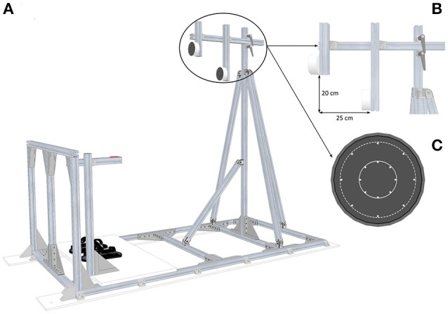
Figure 1.

Experimental setup. (A) Global view of the pointing structure including targets, start push-button and footstraps. (B) Side view of the targets which illustrates the position of the Far targets relative to the Close targets. (C) Front view of the two target sizes: the solid line area represents the Small targets (Ø 4 cm) and the dotted line area represents the Large targets (Ø 10 cm).
