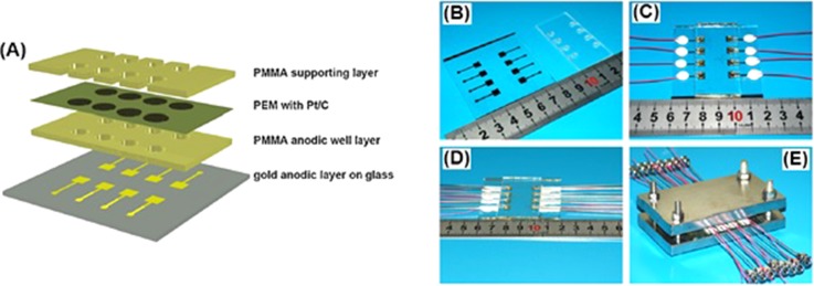
FIG. 8.
(a) Mini-MFC schematic illustration. (b) Gold anodic layer on glass and PMMA anodic well layer. (c) Image of the bonded PMMA anodic well layer on glass substrate. (d) Metal straw sealed by silicon rubber to the anodic layer. (e) Assembled mini-MFC. Reproduced with permission from Chen et al., Biosens. Bioelectron. 26, 2841 (2011). Copyright 2011 Elsevier.

