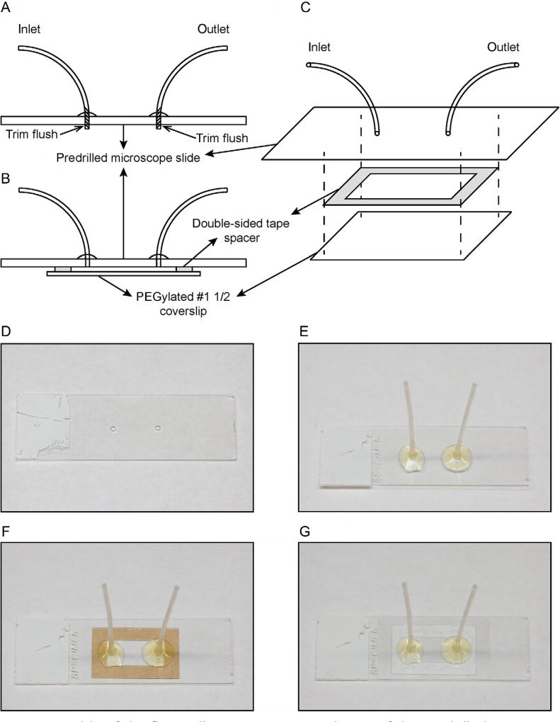
Fig. 6.
Assembly of the flow cell. (A) Cross-sectional view of the predrilled microscope slide with inlet and outlet tubing attached. (B) Cross-sectional view of the assembled flow cell, where the double-sided tape spacer is sandwiched between the slide assembly and the PEGylated coverslip. (C) Exploded view of the flow cell assembly. (D) Microscope slide with predrilled holes. (E) Microscope slide with inlet and outlet tubing attached. (F) Microscope slide with inlet and outlet tubing and rectangular double-sided tape spacer (brown). (G) Complete flow cell assembly with glass coverslip attached to the microscope slide.

