
Figure 7.
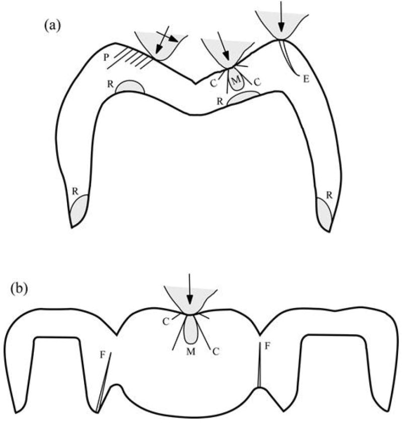
Schematic diagram illustrating various fracture modes in all-ceramic (A) crown and (B) FDP structures: axisymmetric cone (C) and median (M) cracks; partial cone (P) cracks; edge chipping (E) cracks; radial (R) cracks at cementation surfaces; flexure (F) cracks at connectors. Linear-trace cracks (C, P, E, F) extend out of the plane of diagram, shaded (R, M) cracks extend within the plane of diagram.
Modified from Zhang Y, Sailer I, Lawn BR. Fatigue of dental ceramics. Journal of Dentistry 2013; 41(12): 1136; with permission.