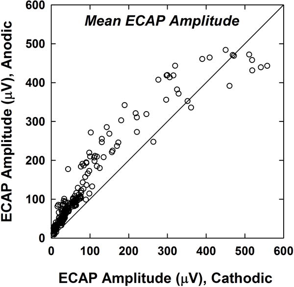
Figure 3.

ECAP amplitudes for anodic-leading compared to cathodic-leading stimuli. Each dot represents the mean ECAP amplitude across the SOE pattern for one probe electrode for one subject (14 probes per subject; 224 total data points). The diagonal line denotes equal amplitudes for both polarities. Data points above the diagonal line represent larger amplitudes for anodic-leading stimuli.
