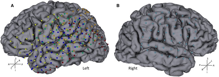
Fig 1. Electrode locations.
A) 5 patients with left grids. B) 1 patient with grid on the right (subject 6). The individual anatomical (MRI and CT) data were co-registered to precisely localize the positions of the intracranial electrodes. Electrodes (represented as balls) were manually assigned after automatic electrode position segmentation. Each color represents one subject. Individual data were coregistered between the five subjects to obtain a single group map with the electrode locations. Note that there are matched electrode locations between subjects with an extensive coverage of both hemispheres. L/R, A/P and S/I stands for left/right, anterior/posterior and superior/inferior respectively.

