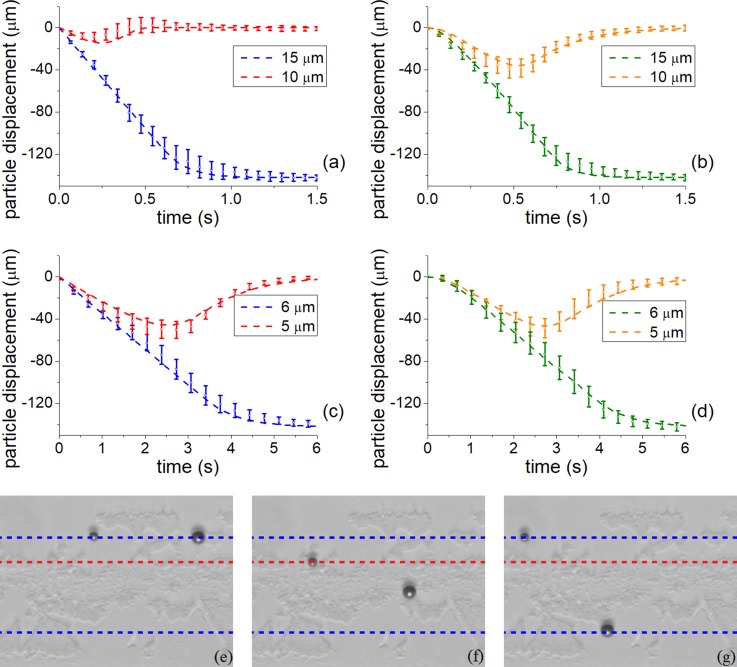
FIG. 5.
Experimental and analytically derived particle trajectories for (a) and (b) 15 and 10 μm, and (c) and (d) 6 and 5 μm diameter polystyrene particles. Left column (a), (c) corresponds to jump modulation (−90° to ° to −360°), right column (b), (d) is the continuous linear modulation scheme. Dashed line denotes analytical trajectories, and dots and error bars denote experimental results. (e)–(g) Micrographs showing the separation process for continuous linear modulation scheme for 10 and 15 μm particles, (e) at t = 0 s, (f) after the ramping period, at t = 0.64 s, and (g) at the end of the sorting cycle, t = 1.64 s. Dashed blue lines denote the position of the nodes, and dashed red line shows the maximum displacement of the small particle. Supplementary material video M1 available online.

