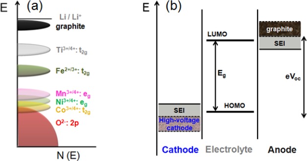
Figure 3.
(a) Positions of the various redox couples relative to the top of the oxygen:2p band and (b) schematic energy levels of an anode, cathode, and electrolyte in an open circuit. The possibility to widen the stability window by the formation of optimal SEI layers on the electrodes are indicated in panel b.

