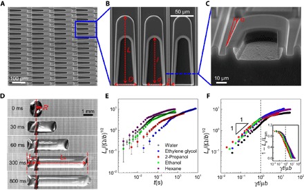
Fig. 1. Design and characterization of liquid diode.

(A) SEM image of the as-designed liquid diode. (B) Magnified SEM image of U-shaped island arrays with the reentrant cavity on one end. L and D are the length and width of the island, l and d are the length and width of the cavity, and s is the opening width of divergent side-channel. Here, L ~ 150 μm, D ~ 50 μm, l ~ 100 μm, d ~ 30 μm, and s ~ 5 μm. (C) Magnified cross-sectional view of the reentrant structure at the inner wall of the cavity. α is the apex angle of the diverging side-channel, and here, α ~ 2.2°. (D) Optical images of time-dependent directional liquid spreading on liquid diode. A water droplet (~5 μl) deposited on the surface propagates preferentially in the direction toward the opening of the cavities and gets pinned in the reverse direction. The rectification coefficient is 5.76. (E) The normalized plot of time-dependent liquid spreading on liquid diode. (F) Rescaled plot of the data summarized in (E). The droplet in the later stage exhibits a logarithmic slowing-down kinetics as evidenced in the semi-log plot of 1 − Ls/Lsm versus t/τ (inset), where Lsm is the maximum spreading length.
