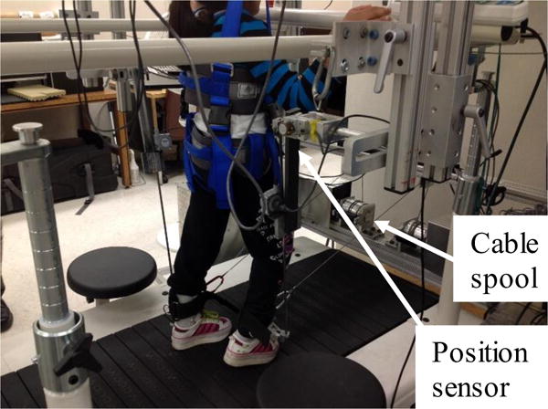
Figure 2.

Experimental setup for the robotic assistance/assistance treadmill training. Two motors and cable spools are attached to a fixed frame located in the front of the treadmill, and are used to apply a controlled assistance force to the legs at ankle, and two are attached to a frame located at the back of the treadmill, and are used to apply a resistance force to the legs. A computer is used to control the coordinated movement of 4 motors.
