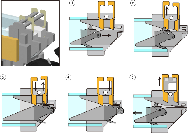
Fig. 2.
Automated self-latching. Top-left panel shows a 3D rendering of the latching mechanism (details of the components and how they are assembled are provided in Supplementary Fig. 3). Panels 1–5 (circled numbers) show the sequence of steps leading to self-head fixation: (1) the head-plate (black bar on mouse head, Supplementary Fig. 1) is progressively restrained by narrowing rails (gray converging lines, Supplementary Fig. 3). (2) The forward motion of the head-plate mechanically lifts up the first pair of latching pins. (3, 4) The first pair of pins then lowers by gravity, and the continued forward motion of the animal similarly lifts up and down the second pair of latching pins, leading to the final self-head fixation (4). During 3, 4, small tilt and forward movements are allowed that reduce the probability of a “panic” response due to a sudden head fixation. (5) When the task session ends, a computer-controlled servo motor actuator lifts up both pairs of latching pins and releases the animal (Supplementary Fig. 4). Original technical drawings edited with permission from O’ Hara & Co., Ltd.

