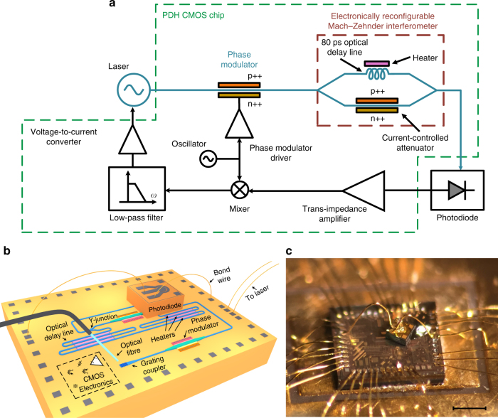
Fig. 1.
The integrated Pound−Drever−Hall laser frequency stabilization system. a The block diagram of the reported Pound−Drever−Hall (PDH) chip implemented in 180 nm GF7RFSOI CMOS silicon-on-insulator process. The laser output is phase modulated using a p-doped-intrinsic-n-doped (PIN) phase modulator, passed through the electronically reconfigurable Mach−Zehnder interferometer (MZI) with 80 ps delay imbalance, and photo-detected. The photo-current is amplified and converted to a voltage using a trans-impedance amplifier (TIA) and mixed with the same electrical signal used to phase modulate the laser. The mixer output is filtered, amplified, converted to a current and injected to the laser gain section to lock the laser to the notch in the MZI frequency response. The output of the voltage-to-current converter, the read-out signal, is asymmetric with respect to the frequency of the notch in the MZI frequency response, . Therefore, the read-out signal indicates both the difference between the laser frequency and and whether the laser frequency is greater or less than (Supplementary Note 1). Note that the modulation sidebands are essential to detect the sign of the read-out (error) signal required to tune the laser toward . b The structure of the reported PDH system. c Micro-photograph of the CMOS chip with a photodiode mounted on top. The details of the integrated CMOS chip are included in Supplementary Note 5 and Supplementary Fig. 6. The hybrid integration of the photodiode chip with the CMOS chip is discussed in Supplementary Note 8. Scale bar, 0.5 mm

