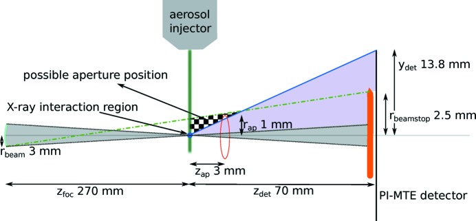
Figure 1.
Schematic of the experimental setup showing relevant distances. The upstream scattering sources are modelled as an incoherent source of radius  located a distance
  from the sample. This is the size and position of the beam at the last focusing optic, which acts as a source of scattered radiation of greatest angular extent when viewed from the sample. Given a beamstop of radius
  and a detector half-width
  , both located
  downstream of the sample, the checkered area shows the region where the aperture can be placed in order that the parasitic scattering does not reach the detector surface. The square aperture used here had a half-width of
  and was placed a distance
  downstream of the sample position. Within the checkered region, the penumbra of the aperture from the incoherent source (indicated by the green dash–dot line) maps to the beamstop and the diffraction from the sample on the detector is not shadowed by the aperture (blue line and purple shaded area). The focused (coherent) X-ray beam is depicted by the grey shaded area. The aerosol injector, shown schematically, directs samples towards the beam focus. The diagram is not drawn to scale.

