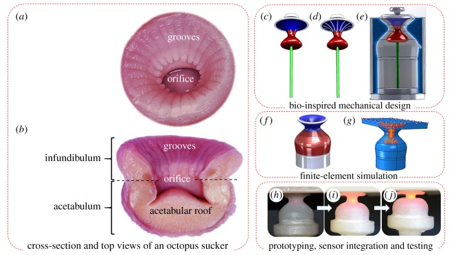
Figure 2.
An overview of the methodology for bioinspired design and implementation of the anchoring module. (a) The top view of an octopus sucker with grooves on the surface of the infundibular portion. These radial grooves not only allow the pressure generated in the acetabular chamber to be transmitted to nearly the whole sucker–substrate interface thereby increasing the firmness of the anchor, but also facilitate the detachment process. (b) The cross section of the sucker showing its biological structure. (c) CAD design of the internal part of moulds without groove structures. Note that the straight rod in the mould's CAD model creates a channel for an optical fibre to be passed through at a later stage. (d) CAD design of the internal part taking into account the radial grooves in the natural suckers (number of grooves = 12, depth and width of grooves = 500 µm). (e) The external part of the mould. (f) The CAD design of the anchoring module with an infundibular part (blue), an acetabular part (red), and a rigid base creating a stable platform for testing (silver). (g) The FEA Abaqus simulation models the vacuum pressure inside the anchoring module as a uniformly distributed pressure load. (h) The fabricated anchoring module featuring a stiffness gradient in its mechanical structure is held tangent to the contact surface (vacuum input and sensor: off). (i, j) The gradual attachment to the contact surface (vacuum input and sensor: on). (Online version in colour.)

