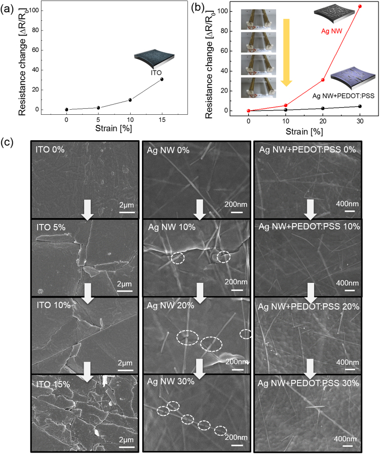
Figure 4.
Resistance change of (a) sputtered ITO electrode on PU substrate and (b) brush-painted Ag NW and Ag NW/PEDOT:PSS electrode on PU substrate during stretching. The inset pictures show the stretching steps of the optimized Ag NW/PEDOT:PSS/PU sample. Insets of (a) and (b) were drawn by using a RHINO drawing program. (c) Surface FESEM images of sputtered ITO, brush-painted Ag NW, and Ag NW/PEDOT:PSS hybrid electrode before and after sample stretching.

