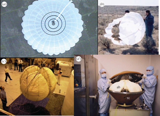
Figure 6.
(a) Main parachute (10 m diameter) imaged during a parachute test (see [9] for details). (b) Pilot parachute testing in New Mexico, 2002. (c) Airbag composed of three segments–during drop testing at Johnson Space Center, 2002. (d) Probe aeroshell during vibration testing at Atomic Weapons Research Establishment, UK 2003. In addition to the lander itself, the front shield (fs) and rear cover (rc) may have been identified in HiRISE images; note the fs is fitted with an inner highly reflective aluminized Kapton multilayer insulation; ab, airbags.

