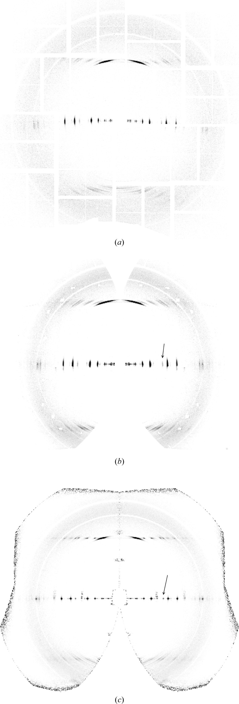
Figure 4.
Averaged diffraction patterns (a) in detector space and (b) mapped into cylindrically averaged reciprocal space, using a tilt of 10° for each pattern. (c) Averaged diffraction pattern in reciprocal space after re-orientating each pattern in φ and β as described in the text. The arrows in panels (b) and (c) show the equatorial reflection used to evaluate the orientation, as described in Section 4.4.

