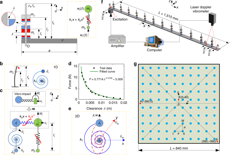
Fig. 2.
Configurations of the NAM beam and plate. a Lateral view of the meta-cell with its parameters; the blue and red parts represent three magnets. The gray rectangle with length a is the principle beam/plate, and the columniform strut with length l s is used to support the magnets. There is a clearance δ between the strut and the magnet m r. The plot in the dashed box is the equivalent two-degrees-of-freedom (2DoF) Duffing model of the transverse motion of m r. b Equivalent torsional motion of the whole attachment in the xz plane. c Whole equivalent coupling model for the attachment in NAM beam. d Repulsive force–clearance Δ relation of a pair of magnets. e Torsional system in 3D space for the 2D NAM plate. f The NAM beam consists of 12 periodic cells and the experimental apparatus. g The 2D NAM plate consisting of a square thin plate and 10 × 10 periodic attachments represented by blue points. In f, g, three red points, A, B and E, denote the measurement points, and E is also the excitation point. The positions of these points on the beam are labeled in f. For the plate, taking the center point of the square plate as the origin, the coordinates (x, y) of these points are labeled

