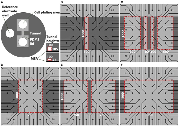
Figure 1.
Designs of the tunnel devices. The PDMS tunnel devices (A) consist of two cell plating areas that are interconnected by tunnels, and a reference electrode well. The two tunnel heights are presented in the lower right corner in (A). The red dashed lines indicate the cross section of a tunnel, in this case 100 μm wide. The numbers in (A) provide the tunnel widths (w) and heights (h) in μm. Tunnels with different dimensions were aligned on MEAs (B–F). Dark gray indicates PDMS bonded to the MEA surface, light grey represents cell cultivation areas in the tunnels and areas under the PDMS lid, while the red dashed lines indicate tunnel perimeters. The numbers in (B–F) provide the tunnel widths (w) and lengths (l) in μm.

