Fig. 6.
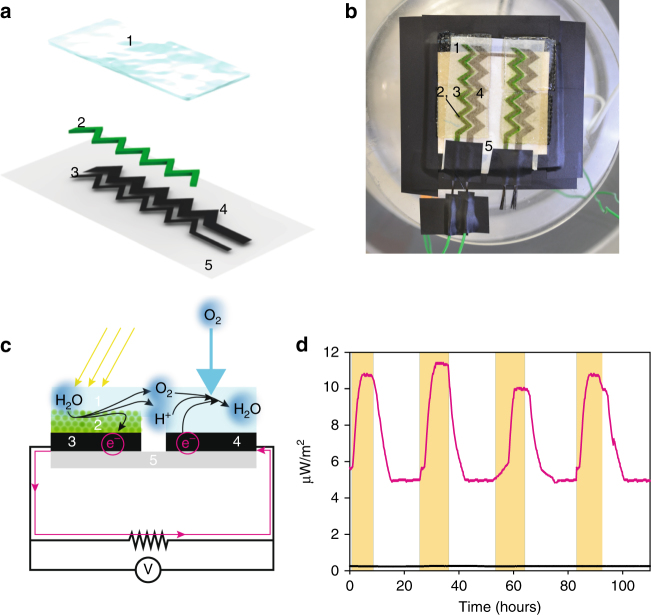
Testing the performance of the fully printed BPV device. a Schematic representation (semi-exploded view) of the printed paper-based BPV cell. Paper support in light grey (component 5); Printed CNT anode (component 3) and CNT cathode (component 4) in black; Printed Synechocystis in green (component 2); Bridging hydrogel in pale blue (component 1). b Photograph of the experimental setup (excluding the potentiostat), showing a pair of BPV modules printed in series. c Schematic representation of the BPV cross-section where electron, proton and oxygen flows are also shown. d Power output measured over 4 days with periods of light and darkness. Light periods indicated by the yellow bars. Magenta trace for inkjet-printed Synechocystis on printed CNT anode and black trace for control experiments without the cells

