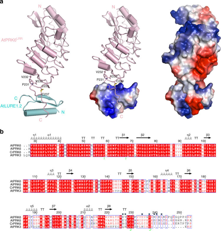
Fig. 2.
Overall structure of the AtPRK6LRR-AtLURE1.2 complex. a Structure of the AtPRK6LRR-AtLURE1.2 complex shown in different modes. Left: both AtPRK6LRR (pink) and AtLURE1.2 (cyan) are shown in cartoon. The disulfide bond Cys229−Cys237 is shown in yellow and three residues capping the hydrophobic core of the last LRR of AtPRK6LRR are shown in stick and labeled. ‘N’ and ‘C’ represent N- and C-terminus, respectively. Middle: the C-terminal loop of AtPRK6LRR binds a positively charged surface of AtLURE1.2. AtLURE1.2 is shown in electrostatic surface. Red, blue, and white represent negative, positive, and neutral surfaces, respectively. Right: interaction between AtLURE1.2 and AtPRK6LRR is both shape-complementary and charge-complementary. Both AtLURE1.2 and AtPRK6LRR are shown in electrostatic surface. b Sequence alignment of AtPRK6LRR, AlPRK6LRR, CrPRK6LRR, and AtPRK3LRR. Conserved and similar residues are boxed with red ground and red font, respectively. Two cysteine residues forming a disulfide bond are indicated by the same green numbers. The AtLURE1.2-interacting amino acids of AtPRK6LRR are highlighted with blue squares on top

