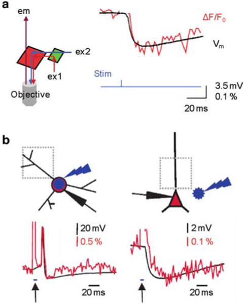
Fig. 4.9.

Combining Vm imaging with ChR2 stimulation. (a) ( Left) Schematic of the optical configuration to achieve this combination; red and blue illumination are used for voltage sensitive dye and ChR2 excitations respectively; IR fluorescence emission is detected. ( Right) IPSP recorded electrically (with a patch electrode) and optically from a the soma of a Purkinje neuron following ChR2 excitation at interneurons located in the molecular layer; modified from Tsuda et al. 2013 (b) Imaging of light evoked action potential in a ChR2 expressing interneuron ( left) and of IPSP in CA1 pyramidal neuron induced by ChR stimulation at interneurons ( right). ( Top) Schematic illustrations of the experiment on the top with site of blue flash and imaging region. ( Bottom) Simultaneous optical dendritic and electrical somatic recordings; arrows indicate blue light application (5 ms); modified from Willadt et al. 2014
