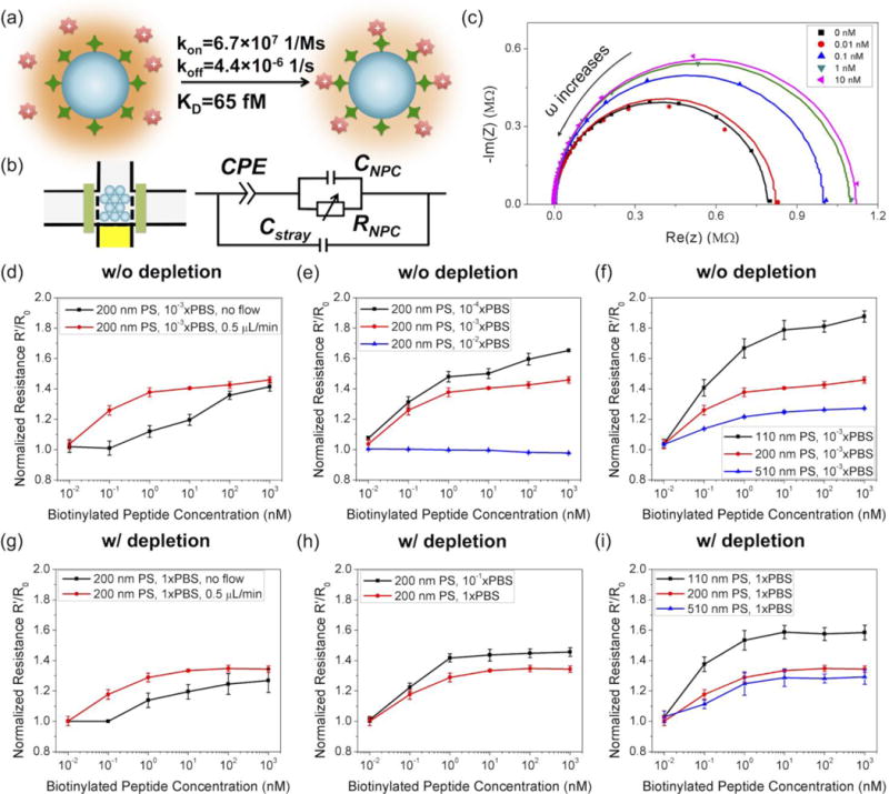
Figure 4.

Detection of a biotinylated positively charged peptide (GRGGRG). (a) Schematics of the biotinylated peptide detection. (b) Equivalent electrical circuit diagram of the device. (c) Complex impedance plot of the chip at different concentrations of peptide (10−3xPBS, without depletion). (d–f) Detection of the peptide in low ionic strength buffers without depletion. (g–i) Detection of the peptide in high ionic strength buffers with depletion. Samples were injected at a flow rate of 0.5 μL/min for 15 min, unless otherwise specified.
