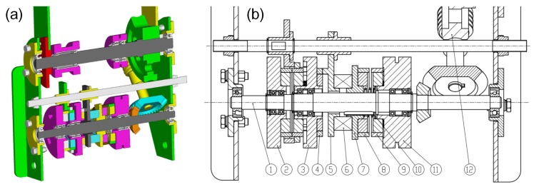
Figure 13.
The illustration of the shoulder joint. (a) shows the 3D model section of the manipulator shoulder joint. (b) shows the manipulator shoulder joint in detail. The part number in this figure is used throughout the paper. ① Transmission shaft for transmitting the power to the shoulder joint. ②, ③ Switch pulleys, for switching power. ④ Switch cam, fixed with the switch pulley for pushing the follower side (Part ⑤). ⑤ Cam follower. ⑥ Thrust bearing, which is fixed with the follower and slider. ⑦ Slider, moving along the axial direction and rotating with the shaft (Part ①) synchronously. ⑧ Master clutch, fixed with the slider (Part ⑦). ⑨ Slave clutch, fixed with the drive pulley. ⑩ Guide key. ⑪ Drive pulley, driven by the drive motor. ⑫ Worm and worm gear.

