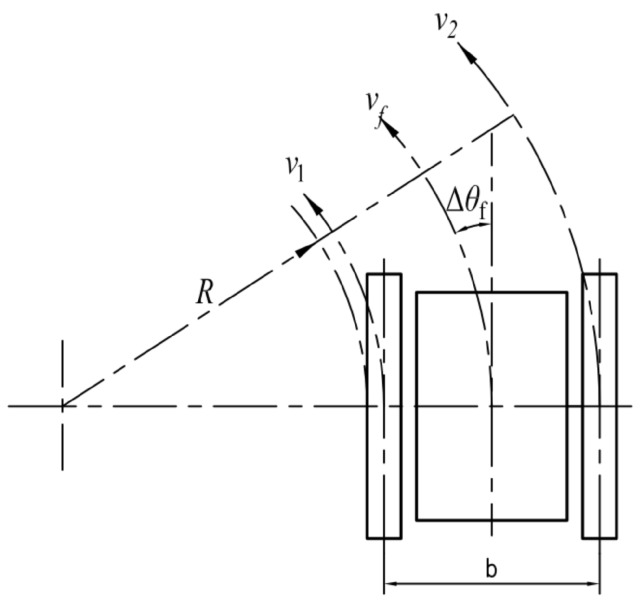
Figure 25.
The illustration of the robot motion parameters. In the figure, R represents the radius of the robot when turning, represents the deflection angle relative to the current traveling direction, and represent the speed of the left and right traveling subassemblies, represents the speed of the robot and b represents the distance between the left and right subassemblies.

